Strange!! HP Pavillion G6 2000, first BIOS crash, then motherboard dead ??

serious_electron

New Member
Reaction score
1
Location
Canada
Hello Everyone!

To start with, I am basically a noob when it comes to component level repairs. I identify myself at a stage where I am able to recognize some SMD components by shape, size and color. I know the very basics of testing the voltage by hooking the multi-meter probes and that's it.

Keeping that in mind, I will try to explain my situation in best possible way --

I own a 5 year old HP Pavillion G6 2288CA, a laptop known for its overheating.
I have used the machine lots in the past and sometimes left it on for days continuously.

After 2-3 yrs, I started getting message whenever I boot, the the Motherboard fan has malfunctioned and the computer will shut down to prevent damage. I have regularly serviced my laptop and cleaned my fan and managed to get the fan going. However, whenever I go to places/countries that are warm/hot, and keep laptop with its bottom touching the bed, or my lap.. then the laptop shuts down. And upon booting up, it gives the error that the system shut down due to overheating and to prevent the damage etc.

Now recently, from last couple of years, all my laptops have been compromised (hacked) and have had many virus attacks. The hackers even fiddled with the startup settings.

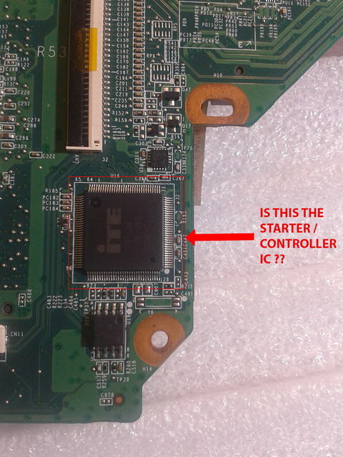
But things took much serious turn when after shutting down the laptop when I restarted, I was shocked to see RESTORING BIOS screen. And most of the times, the restoration failed. And then when the laptop once again starts, the screen is dead blank (no signs of life) but only the caps lock LED blinks.

After doing some research on restoring BIOS etc, I managed to get inside the system by removing hard disk, and pressing windows+B key on startup to enter BIOS restoration. However it was a long struggle.

But then, one day once again by system shut down (as there was no battery and the charger cable came out). And upon starting, the same.. I was taken to Restoring BIOS screen and after that got the message "BIOS RESTORATION FAILED". I then tried to again remove the hard disk and follow the same process, after re-booting, I was taken to BIOS RESTORATION page and it said "Initializing ... " I waited for 5 minutes and kept the laptop on the chair and went out.

When I came back after 5-10 minutes, I saw the system was shut down. When I pressed the power button, I WAS SHOCKED TO SEE THAT THAT LAPTOP WAS COMPLETELY DEAD. NO SIGNS OF ANY LIFE WHATSOEVER. NOT EVEN CHARGER LED.

And I could notice that the laptop base of very warm.

At this moment I could sense that there is something serious. I took out the motherboard finally. Did some research and went through some videos on youtube. After which at this moment I could sense that this seem to be some problem related to MOSFET's or Power Supply (on the motherboard).

There is a small LED on the DC Charging socket that lights up everytime when the charger is plugged into it. But even that's dead! So I guess this doesnt looks like to be a problem of the BIOS.

I managed to download the schematics of my motherboard after doing a lots of search. The name of the file is quanta_r53_r1a_schematics (last on on the bottom).

Now I have thoroughly checked the charger, and there seems to be no fault in the charger or the charging socket as the multi-meter is reading full 19.75v

I have also checked the BIOS chip and the voltage at pin 8 is around 3.27v

Did some visual inspection but couldn't identify anything significant.

I then did two important things :

Measured voltages at the MOSFET's
Did Continuity tests on both 8 pin and 3 pin MOSFET's

As for the continuity tests, this is how I tests MOSFET's to identify if they are short--

8 Pin MOSFET Continuity test :

I test all the 4 pins of the drain (on one side) for continuity beeps. I test 3 pins of the source + 1 pin of the gate (on the other side) for continuity beeps. If they all beep, then I determine that both Gate and Source are short.


3 Pin MOSFET Continuity test :

I test both gate and source for continuity and if they beep, means there is a short

Here I am posting the results of testing some common MOSFET's voltage readings and continuity tests :

PQ50 (MB20 N03 CEI 1402) DRAIN-19.75V , SOURCE-0V , GATE-0V
(both source and gate are shorted)

PQ53 (MB20 N03 CEI 1185) DRAIN-19.75V , SOURCE-0V , GATE-0V
(both source and gate are shorted)

PQ55 (MB20 N03 CEI 1185) DRAIN-0V , SOURCE-0V , GATE-0V
(both source and gate are NOT SHORTED)

PQ44 (MB20 N03 CEI 1123) DRAIN-19.75V , SOURCE-0V , GATE-0V
(both source and gate are shorted)

PQ42 (MB20 N03 CEI 1402) DRAIN-19.75V , SOURCE-0V , GATE-0V
(both source and gate are NOT SHORTED)

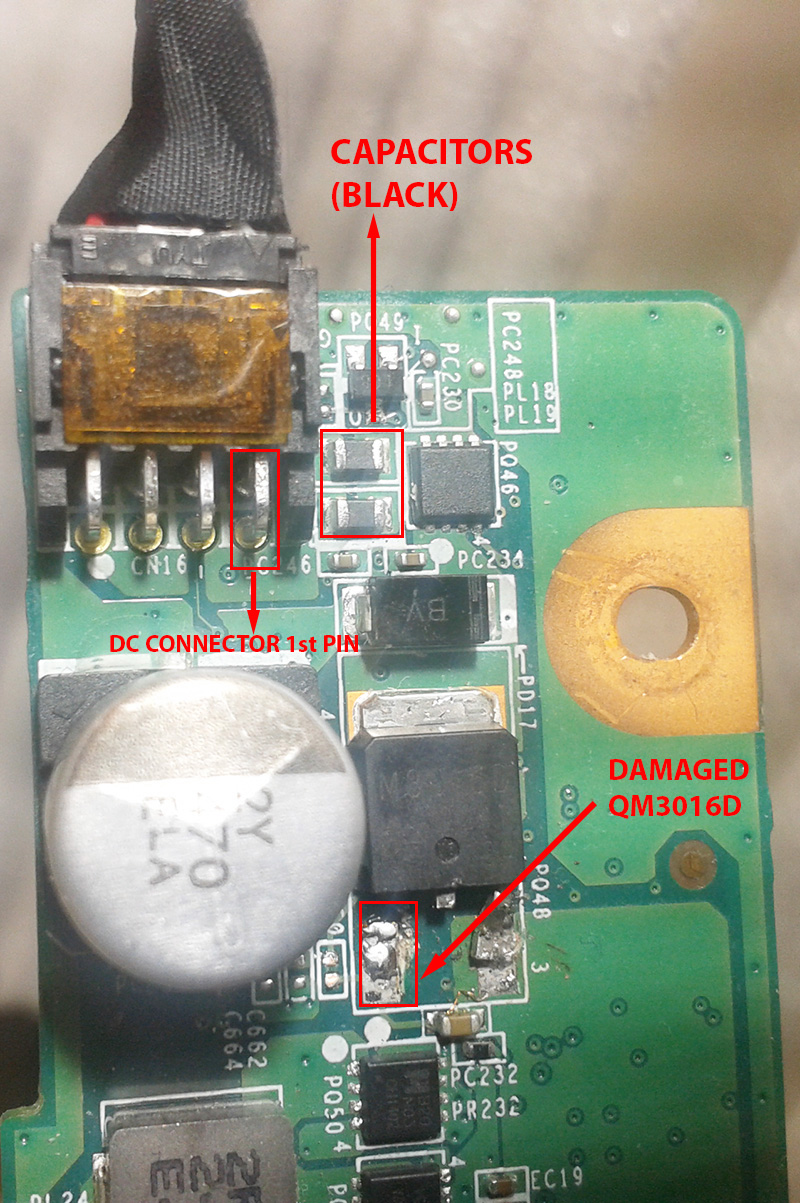
I am attaching the images with proper markings to understand better :

Front Side
https://ibb.co/hXaJsp
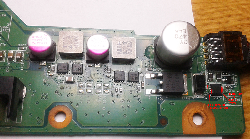
Back Side
https://ibb.co/ipdSk9

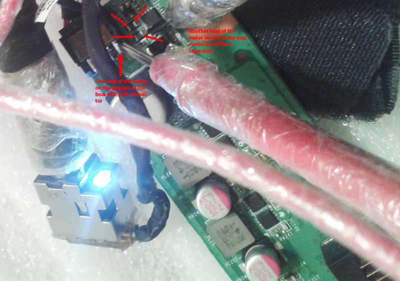
NOW HERE IS SOMETHING IMPORTANT:

WHENEVER I PUT ONE PROBE OF MULTI-METER TO POSITIVE OUTLET PIN OF THE CHARGING SOCKET AND OTHER PROBE OF MULTI-METER ON THE DRAIN OF PQ50 , OR THE SOURCE OF PQ48, THE DC CHARGING SOCKET LED LIGHTS TURNS ON BUT THE BOARD DOESN'T TURNS ON (AS I CAN'T SEE THE FAN RUNNING) UPON PRESSING THE BUTTON.

I also noticed some short capacitors (small ones) located near the CPU panel. As they beep when both probes of the multi-meter are put on either sides.

I want to take this as a learning project, but also need my system up and running ASAP as my work is stalled. I am not sure if by replacing all these MOSFET's would help. But if I need to place and order, are these the right models for replacement?

https://www.aliexpress.com/item/EMB2...708103847.html

Also, I currently don't have any power supply to test and identify the component by increasing amps and seeing the short (a process I don't fully know). But can try arranging one if I am sure that this problem can be resolved.

Also, if I try changing the motherboard (for now), will there be any problem in booting windows (please note that the operating system is default factory installation of Windows 8 by HP. And I don't even have the recovery discs for it).

Would appreciate help at the earliest.

Motherboard Model : DA0R53MB6E1 REV:E R53(MAIN1)IMG_20180826_035949.jpg (MAIN2)IMG_20180826_045915.jpg (MAIN1)IMG_20180826_035949.jpg (MAIN2)IMG_20180826_045915.jpg
 
it certainly sounds like the motherboard is goosed.

you can try repairing it yourself, however I would do one of 3 things.

outsource the repair to a tech or company which does these types of repair.

swap the motherboard completely.

you will need to download and install 8 or 10 again. you should know where to get that from. ensuring that you don't overwrite the existing data.

purchase a new laptop and effect a full data transfer.

Hello :

THanks so much for your response.

I don't mind replacing the motherboard. However, MY ONLY CONCERN IS THAT I DON'T WANT TO FORMAT / WIPE THE HDD AFTER REPLACING THE MOTHERBOARD. That's because the original HP notebook HDD has factory Windows 8 installed, and unfortunately, I have not made any backup's of the recovery discs from the HP recovery disc creator. So even if i replace the motherboard with a new one, is it still possible to boot back into the OS and make the recovery discs?


I am guessing that since the old motherboard BIOS with different, not sure if there would be any mismatch if i try to boot after replacing the motherboard in back into my old factory installed HP windows 8.


Would be great to hear your advice.


Thanks.
 
That's because the original HP notebook HDD has factory Windows 8 installed
Might have some issues activating Windows on the new board if the new board is not programmed with a Win 8 key.
I have not made any backup's of the recovery discs from the HP recovery disc creator. So even if i replace the motherboard with a new one, is it still possible to boot back into the OS and make the recovery discs?
An actual tech would not use the HP recovery disks and install the crap that comes with a factory install. You can still install 8 from an ISO that you can still legally download for free.

it certainly sounds like the motherboard is goosed.

you can try repairing it yourself, however, I would do one of 3 things.

outsource the repair to a tech or company which does these types of repair.

swap the motherboard completely.

you will need to download and install 8 or 10 again. you should know where to get that from. ensuring that you don't overwrite the existing data.

purchase a new laptop and effect a full data transfer.

I would just replace this computer. it is not worth the money or hassle for those G6 computers. You will end up only getting a used motherboard with the same issue soon down the road.
There are many refurbished business class notebooks out there that will last longer and perform better than that buggy consumer grade junk.
 
Might have some issues activating Windows on the new board if the new board is not programmed with a Win 8 key.

I've always heard that a new board will activate under the old key as long as processor, HDD (and memory?) are the same. Never tried it though. Usually a MB goes and game over.

To the OP - Are you aware of FABs (discussed emphatically elsewhere in these forums)? It will pull the drive contents, and put them back on another machine.
 
I've always heard that a new board will activate under the old key as long as processor, HDD (and memory?) are the same.
New board is a new computer to MS. You should be able to jump thru MS hoops and get it reactivated because of a board replacment not an upgrade board. A replacement board "should" have a embedded bios key for Win 8 if the replacement board is from the same generation and someone did not erase the bios key.(read somewhere it is possible but never had to do that never a reason to do so)
 
Now I have thoroughly checked the charger, and there seems to be no fault in the charger or the charging socket as the multi-meter is reading full 19.75v

I have also checked the BIOS chip and the voltage at pin 8 is around 3.27v

Since you have your voltage at the bios chip then your 19 volt rail is up and running fine.

Is your 5 volt rail up and running? Check at a USB port to see

Do you also have 3.3 volts at the power on button? Thats important.

As per the caps you suspect to be short did you check to make sure they are just in parallel and perhaps one is bad causing you to believe they are all bad?

You seem to make some really good points. Since I am just a starter and a newbie, could you mind telling me how and where can I locate the 5v rail? Can the voltage be measured on every USB socket?
 
You seem to make some really good points. Since I am just a starter and a newbie, could you mind telling me how and where can I locate the 5v rail? Can the voltage be measured on every USB socket?

The keyboard, USB ports run off of 5v. So, You can check for voltage there.

Keep in mind that a motherboard is made up of 2 things - small power supplies and integrated chips. The main rail is about 19volts. This rail goes so far and then is broken down to the individual power requirements. When you plug in the charger or battery there are 3 main rails that have to be present - 19v, 3.3v, 5v. I will add that I have ran into some boards that the bio's 3.3 volt is not present until turned on.

Each power supply circuit consists of two mosfets, A large output cap, a inductor (or coil) and resister (current limiting). When you look at your Motherboard you will pretty much always see two mosfets and they will be near a coil and a large metal cap capacitor. The mosfets just act like a switch. Sometimes they will have one mosfet on one side of the board and the other on the other side of the board. You can check the output of those to see what voltages they supply and you can then find what circuit they provide power for - processor, Memory, bios, USB, Screen ect...

Keep in mind that sometimes they combine the two mosfets into a single chip. This is found in newer laptops.

The main IC that makes everything work is the Startup chip. If it senses some power supply is not working right then it will keep the laptop from turning on.

Grab your meter and add power to the laptop and check for voltage on one of the USB pins. There will be 4 of them. You can use any ground point you want. If your not getting power at a USB port then disconnect power and put your meter in continuity mode (beep mode ) and track back the USB traces on the board from component to component. You will end up at its power supply circuit. Then Check the output of the power supply circuit for the USB. No output? Is it being told NOT to turn on? Depends on the startup chip. Look up your startup chip and look for the output for 5volts. Most of the time you will find your problem in a bad small (i.e. 0402 size) capacitor that has shorted to ground. These caps help filter dirty voltages and keep them clean.

If you have all your correct voltages and everything seems to be working fine but laptop will not come on then suspect the startup chip is the problem and needs replacement - exact model replacement. Also, There are a few Startup chips that have the bios built into them. This is much harder to replace because of that.

USB port ------> ic_usb_controller_ ---> 5volt_power rail -----> (p/s for 5volt rail) -----> 19volt rail

Just determine that you have all power rails needed to turn on the laptop. 19v,5v,3.3v. If you do not then find which is failing and where. Not as hard as it sounds because we know certain circuits use certain voltages:

19v --- whole board - main rail.
5v --- USB, Keyboard other devices similar to these that are on the usb bus.
3.3 -- bios, Power button, Memory.
1.5v -- processor

Hope this helps,

Hello:

Thanks for your detailed and accurate response. Sorry for my delay in response, was busy with something all this while. I can recon all what you mentioned in your response very well. Here is what happened with me :

I tried de-soldering MOSFET QM3016D (that's near the DC Jack connector socket at the starting of the motherboard), but unfortunately one of it's pin's got broke from inside (guess due to excessive heat from the soldering iron), as I didn't had an SMD heat gun (I have ordered one now, and it's on its way).

I am attaching the pics so that the situation gets clear

01.jpg


Ok... now something very important :

As you can see in the pics, I noticed the nearby 2 capacitors are totally BLACK in color. Now I am not sure if they are naturally colored like this or have been toasted. (have marked these 2 capacitors in red). Also, note that I have marked on of the DC connector pin in red (1st PIN).

Now when I put the meter in the continuity mode, attach the charging cable into the socket and then put ONE of the multi-meter leads on ANY of the 2 capacitors contacts (any one of the 4 available), and put the OTHER multi-meter lead onto the 1st pin of the DC Connector (as marked), then all of a sudden the DC Charging LED glows! But even after that the motherboard fan doesnt turns on upon pushing the power button.

I tried to explain this in detail with this picture :

02.jpg


I tried checking the voltage/s on the USB socket/s , but unfortunately it reads 0.

I have ordered the QM3016D along with the hot gun, and can try re-checking the voltage at the USB ports after I replace the damaged QM3016D with a new one.

Look forward to your valuable advice.
 
I have also checked the BIOS chip and the voltage at pin 8 is around 3.27v


Just knowing you have voltage on the BIOS means your 19v rail is intact.

To make sure, When plugged in to charger :

1 Do you have a charge or power light?
2. Do you see a momentary fan spin?
3. Does the processor get warm?
4. Make sure again that you have 3.x on the power button and bios.
5. Feel your ram- is it getting hot?
6. Put your finger on the start up chip - is it hot?

Report those back here
 
I didnt see your last post. Sorry

Next to the blown out mosfet is a missing resistor. The track goes down to below your red square and to the cap to ground.

Capacitors can be black or tan. Sure they are not current limiting resistors on the input?

Find the schematic on that thing and also go to ebay and source a replacement MB. Check the cost. Lets balance this out. If that replacement motherboard is available and its less than 150.00 then its the quickest way to get you up and running.

Hello :

Thanks for your fast reply. The resistor slot near the damaged MOSFET you mentioned is like this from beginning. I have not desoldered anything from it. Here is the schematic I manage to source -- (this motherboard seems to be based on Quanta R53) http://www.s-manuals.com/notebook/hp_pavilion_g6 (please select the last one from the link).

Now note that once you open the schematics, I noticed that I can rarely spot an in / out voltages mentioned for components. So it's virtually impossible to determine correct readings.

Also, what intrigues me the most is that how come the charger light all of a sudden starts glowing when I switch the multi-meter to continuity mode and put one lead on the 1st Pin of the DC connector on the board (as shown and marked in the pic above) and another lead on any of the available 8 contact points of the capacitors (as shown and marked in the pic above).

As for the replacement, as of now, I am trying to arrange a working laptop to continue with my work. And I would like to take this repair as an learning exercise. Hopefully back and forth replies through forums will help me track down to the fault.
 
Pull PQ46 from a donor board. They are very common. Just come close on the specs. Since its a mosfet you are only concerned about voltage handling. Any similar will do.
 
Replace PQ48.
Just plug charger in.
Check for voltage on PQ46.
Turn on laptop and hold your finger on your startup chip - PU8 which should be a TI BQ24728
Data Sheet ---> http://www.datasheetcafe.com/bq24728-datasheet-texas-instruments/
If your startup chip gets WARM then it might be damaged.

Did you say you had the schematic on it? If not I do.

Hi ..

Here are the voltage readings for PQ46 (see the below image for more clarity ) :

(The font on image maybe small, so in brief, the LEFT side pins reads 19.70v and the RIGHT side pins reads 0v )

pq46.jpg


As for the starter chip, am not sure if this is the right one?? It reads something "ITE it8518e". It Doesn't gets warm when the charger is plugged in.

starter.jpg
 
Ok, Thats the starter chip alright - long day - sorry. Your lucky as that one does not have the bios built into it like the emc ones do.

Your first pic of PQ48 showed the legs melted off. Later pics show a perfectly good chip. Did you already replace it?

I get tired of typing "continuity" so I will just say "beep" instead:

PQ46 is your first mosfet on the 19v rail. The second one is PQ48. The idea is that PQ46 will blow before PQ48. They help limit voltage on the main rail.

To be sure, There are no "Points" on a schematic or board. They are pins. In your picture you tell me no voltage at these points. Well, That doesnt tell me anything. Find the pin numbers so we do not get confused.

With the charger plugged in, Check for voltage on the 3 source pins and then see if they are on the 4 drain pins. If they are not then check the gate voltage. If no voltage on the gate then disconnect power and check for a short to ground on the gate. If none then it might not be being told to turn on. Check that at PQ18.

If you have voltage at the drain of PQ46 then see if you have voltage at PQ48 pin 4. You should. If you do not then probably one of the caps died.
 
After that, Find the power button cable connector and with the power plugged in - check for 3 volts on one of the pins. Should be there. If its not then there is a problem with the 3v rail in the area of the power button. Double check 3v on the bios once again.
 
Your first pic of PQ48 showed the legs melted off. Later pics show a perfectly good chip. Did you already replace it?

Hello,

I have to say, your observation is great! You are right, that above pic is slightly old pic. (Was taken days before I tried to remove PQ48 unsuccessfully by soldering iron, and in the process ended up breaking it's one leg).

For rest of the voltage readings, I will reply back soon with the pictures.

Thanks.
 
Last edited:
Hello... sorry, disappeared all this while. Too many things going on. Wondering if anyone still getting this post? I have all the necessary equipment now and am ready to start again :)
 
Back
Top