RSTP question

DocGreen

Well-Known Member
Reaction score
44
Location
South Bend, IN
Working for a hyper-local WISP, and was trying to complete a loop in the network to provide some redundancy. Doing so broke the internet until I removed the loop. Hoping someone here can give a little guidance. 😬

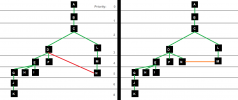
The image below shows what I'm trying to do. Each box is a switch (A is the gateway). The RSTP priority is shown as 1-8 for simplicity (but I understand the proper numbering/increments of 4096). The original topology is on the left, with my attempted (failed) loop shown in red. I'm trying to link switch N back to switch D to create a loop.

I think where I failed was setting RSTP priority on switch N one hop higher than switch M.

I think the correct configuration would be to set switch N's priority to the same as M, because once the loop is complete they will be the same number of hops from the router. (shown on the right)

Can anyone confirm?
1651607060098.png
 
First step....don't use auto configure for STP, as they all default to priority of 32768. Choose your root bridge..and manually set it as the root (32768 minus 4096) (I'm guessing B?)
Yeah, B is the first switch (A is a router). I should have written out the priority for each level, but I was lazy. Basically it's...
1 - 8192
2 - 16,384
3 - 24,576
4 - 32,768
5 - 36,864
6 - 40,960
7 - 45,056
8 - 49,152

The current topology without a loop has switch N at the end of that branch, with priority set at 36,864.
I want to connect switch N (36,864) to switch D (24,576), but doing so with the current settings (left topology) broke the network.

None of the switches are using the default/auto-config. I went through last night and made sure the entire network was set "properly(?)". The full network is quite a bit larger than the topology pictured, but it all follows the same pattern (adding 4096 for each hop from the root).

I'm really hoping that I just need to adjust the priority on switch N... But to be fair, my experience with RSTP is limited to Googling "WTF is RSTP", so I'm literally flying by the seat of my pants here. Waiting for the middle of the night when demand is at a minimum for my 2nd attempt. I'm honestly shocked that nobody complained about the middle-of-the-day outage earlier. 😬
 
What the heck are you building. Are there edge ports all over? Honestly, try to keep this core, distribution, and edge. If you are 8 levels deep for Layer-2 you have a real ****-show on your hands.

Personally, my cores route layer-3 only to my distribution layers whereby I use routed LACP links to do this. The distribution layer is where I terminate all of my layer-2 VLANS to all of the edge closets or servers. For these links I also use LACP.

RPVSTP+ is great, but keep in mind this is for every VLAN. I still don’t like loops because occasionally a network will sometimes hiccup and broadcast storm it seems. My recommendation is to use LACP when you want redundancy, but I don’t see that working here in this mess
It's an entire WISP that I've inherited (Ubiquiti powered), so yeah, there are edge ports all over. Switch C branches off to I think 5 different sites (only 2 are pictured above). Nearly every switch has a client site. Switch D, for example, is at the top of a 144 unit apartment building so E, G, H, I, J, K each have 24 client sites (one switch per floor, 24 apartments per floor).

The topology from D down is a mess because of how construction on that building progressed. Once construction is complete, we'll run a fiber cable from B (core switch), to a new aggregation switch replacing F, and then fiber from there to the switch on each floor.

I was about to say that the only switch shown in that topology that didn't have an edge port was switch C, which is an EP-S16 (outdoor POE switch powering PTP antennas), but then I realized even that switch has a security camera attached to one of the ports, so... yeah. Edge ports all over. 🤷‍♂️
 
Personally, my cores route layer-3 only to my distribution layers whereby I use routed LACP links to do this. The distribution layer is where I terminate all of my layer-2 VLANS to all of the edge closets or servers. For these links I also use LACP.

We've got a ton of VLANS, and a lot of our edge switches have devices from multiple VLANS. For example, here are the VLANS on switch G. 50 is for the building's door controllers, 101 for management, and 300 is for internet customers (apartment tenants).
1651715491299.png

I could have separate switches for each VLAN, but that would have required additional cabling, and at least double the number of switches. We're already at 9 switches for just that building as it is.
 
Here's a little more insight into the topology. Each of the points is a different site, and most of the links are 60G PTP WIFI. Each site has at least one client site, some (like the apartment building) have a ton of client sites. Forgive the black boxes. The sites are named with the street addresses in our system.
1651717942063.png


Here's the topology of the core site. Each device on the left side of the box is a switch (except for the router at the top). On the right of the box are PTP antennas linking to other sites. Bottom right are managed battery backups, and each of those links with just text and no device icon are client sites (individual customer).

1651716747827.png


Aaaand just for fun, here's the topology of the 144 unit apartment. A couple things you might notice on in this one: First, there aren't 144 client sites shown. That's because only the first 2 floors are fully complete. The 3rd is waiting for me to finish installing airCubes in the apartments, 4th is waiting for the electricians to terminate the cabling in the apartments, and 5th & 6th floors are still under construction. The other thing you may notice is the 2 switches at the top are different. That's because we had to start ordering Aruba switches because all of Ubiquiti's stuff is out of stock. 🤬

1651717681343.png
 
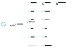
I don't like the L, M, N setup. Daisy-chaining switches is a bad idea.. It would be far better to stack those vs have each frame processed three times as it comes in and out of all of those chassis.

As for a VLAN per switch, usually that is not done unless there is routing. The typical thing to do is Trunk multiple VLANS over an interface.

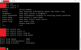
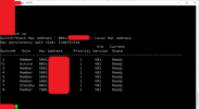
A stack also takes care of link redundancy within the stack because it is a ring.

Here is an example of a stack:
1651753234030.png


1651753406998.png
 
Last edited:
Back
Top