Smooth Gecko
New Member
- Reaction score
- 0
- Location
- Queensland Australia
This is a curly one that I put my hand up for. ")
An industrial backplane had blown its CRT monitor and replacements are not around.
The video card manufacturer has produced a new video card and flashed it to output CGA.
A new 15" LCD monitor was also acquired by the previous tech with CGA inputs.
Due to the age of the setup, documentation is slim and the backplane manufacturers have no help available for the product.
I have got the unit to boot with it's customary three beeps and now for the first time in months, something on the screen. The schematics were very hard to read and the 10 pin connecter had been connected incorrectly before I got there.
( I have been on it for three days, the owner just cannot get anyone that will / can help. )
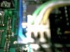
Trouble is, it is just a one centimetre green square in the top left corner.
The OSD does work now, and I have gone through most of the adjustments, but none that are relevant to the issue we have.
The new monitor does have an auto detect and adjust feature that appears to get it right.
(The raster appears well located and the full size of the panel.)
There is a setting that I have not been game to touch.
"Phase" . It is at 0 and just increments.
I am holding out that the computer is working based on:
1 The three beeps that it apparently has always made.
2 If I input some numbers from the touch panel it changes which menu buttons etc beep
and react to button presses.
3 Some LEDS on the board are displaying when certain inputs are made.
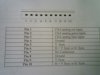
I am using 6 wires from the 10 pin video connector on the card to the 10 pin CGA interface on the monitor,
WIRES DISPLAY VIDEO CARD
2 x Black Ground Ground
1 x Yellow V V
1 x White H/V H H
1 x Green G TTV
1 x Blue B C/V ( Composite Video )
I am lost as to what is going wrong but, feel that the Green is wrong. This is as it was when I was called in except that the wires are now on the other row of five pins on the video card as the Ground bus had been misidentified previously. ( one row of five pins are all connected to the ground bus & the yellow, white, green and blue were all connected to ground as I found it )
Would love to help this guy out, so if anyone has any ideas I would well appreciate hearing them.
An industrial backplane had blown its CRT monitor and replacements are not around.
The video card manufacturer has produced a new video card and flashed it to output CGA.
A new 15" LCD monitor was also acquired by the previous tech with CGA inputs.
Due to the age of the setup, documentation is slim and the backplane manufacturers have no help available for the product.
I have got the unit to boot with it's customary three beeps and now for the first time in months, something on the screen. The schematics were very hard to read and the 10 pin connecter had been connected incorrectly before I got there.
( I have been on it for three days, the owner just cannot get anyone that will / can help. )
Trouble is, it is just a one centimetre green square in the top left corner.
The OSD does work now, and I have gone through most of the adjustments, but none that are relevant to the issue we have.
The new monitor does have an auto detect and adjust feature that appears to get it right.
(The raster appears well located and the full size of the panel.)
There is a setting that I have not been game to touch.
"Phase" . It is at 0 and just increments.
I am holding out that the computer is working based on:
1 The three beeps that it apparently has always made.
2 If I input some numbers from the touch panel it changes which menu buttons etc beep
and react to button presses.
3 Some LEDS on the board are displaying when certain inputs are made.
I am using 6 wires from the 10 pin video connector on the card to the 10 pin CGA interface on the monitor,
WIRES DISPLAY VIDEO CARD
2 x Black Ground Ground
1 x Yellow V V
1 x White H/V H H
1 x Green G TTV
1 x Blue B C/V ( Composite Video )
I am lost as to what is going wrong but, feel that the Green is wrong. This is as it was when I was called in except that the wires are now on the other row of five pins on the video card as the Ground bus had been misidentified previously. ( one row of five pins are all connected to the ground bus & the yellow, white, green and blue were all connected to ground as I found it )
Would love to help this guy out, so if anyone has any ideas I would well appreciate hearing them.