VLAN options - when to use what

HCHTech

Well-Known Member
Reaction score
3,835
Location
Pittsburgh, PA - USA
At the risk of asking a dumb question (never stopped me before!), I have a query about VLANs. Some background:
  • I'm in the SMB market, so don't ever work with multi-thousand dollar switches or equipment. My clients have a firewall at the edge and 1-3 switches
  • Most of the time, the reason I set up VLANs is for guest wireless, IP Phones, or IOT devices
  • I'm self-taught - so my knowledge is the sum-total of my field experience, my own reading, plus a few thousand calls to tech support over the years - haha. I never had a mentor and was never an apprentice.
So, some devices can tag traffic (phones, access points), and others can't. Some switches can be programmed to assign ports to different VLANs and some can't. Obviously, the firewall at the edge can do both a physically separate network, or can be setup for VLANs "under" the main LAN.

If, for example, a customer has a non-converged IP phone installation, you can physically separate the phones by setting up two LANs on the firewall, and have two separate switches - no need for a VLAN at all.

If the device (like phones or access points) can tag traffic, you can setup the VLAN without involving any programming of the switch. You configure the tag on the device(s) and configure the firewall to separate that traffic however you like.

My confusion surrounds why you would choose to program the switch and dedicate a port or range of ports to a specific VLAN. Is this more secure than relying on the firewall to separate the traffic based on the VLAN tag? Is it more efficient because it restricts the broadcast range on the switch? Once you program the switch, do VLAN tags even matter anymore - because traffic is physically separated (presuming you aren't doing anything with that traffic in the firewall other than giving it access to the internet)?

Thanks for indulging me!
 
You can do it physically like you mentioned. For example, if you have a nice firewall with several ethernet interfaces for the LAN side...you can have ETH1 for the production network, say, 192.168.10.0/24, and ETH2 for the VoIP network...say, 192.168.20.0/24, and ETH3 for some other network, like 10.0.0.0/24 for a "guest" network. Firewall not doing any VLAN recognition.

Now, you can have three physically separate switches, not uplinked to each other, only uplinked to those ETH interfaces. This way you don't need VLANs at all, because you're doing physically separate LANs.

Or....you can have 1x bit switch, say a 48 porter. And within it, you can create VLANs. Default VLAN 0 for the production network. VLAN 2 for the VoIP network. VLAN 6 for the guest network.

For the switch ports facing the firewall, you UNtag the VLAN that you want to flow upstream to that ETH port. So, for example, for ETH1 on the firewall for the production network, we'd have default LAN (VLAN0) UNtagged on the port that you uplink to ETH1. And..for the switch port you have uplinked to firewalls ETH2..you would UNtage VLAN2 on that switch port. For the switch port linked to ETH3...UNtag VLAN6.

Or..you can have the firewall do all the handling of VLANs. Each ETH on the firewall can terminate the VLANs, so you can not bother UNtagging the VLAN on the switch facing that port..just leave it with an "all" profile...and it will see that the ETH interface its facing will catch it.

You can even have a single ETH interface on the firewall have VLANs on it...but I do prefer to separate the traffic on ETH ports purely for an efficiency/performance standpoint...even though a single gigabit ETH port likely is far from saturated.

A common scenario that I do on Unifi switches...and Untangle firewalls...

In Unifi, I'll create a corporate VLAN for the VoIP...VLAN2.
I then created a switch port profile, "converged data/voip/with POE."
Default LAN....and tagging VoIP VLAN2, with POE on.

I enabled that profile to switch ports facing offices...that will have a jack in the wall going to the phone and computer...the phone doing passthrough.

On the Unifi switch, say port 1 uplinks to the Untangle ETH1 for internet...I'll leave default LAN on that, no POE.
Port 2 uplinks to the server...so default LAN, no POE.
Port 3 uplinks to the EdgeWater VoIP box. I will set the default network for that as VoIP VLAN2....no POE. This is the Unifi way of UNtagging a VLAN on the port. So in the switch, it knows the VLAN2 traffic will exit there...hitting the EdgeWater VoIP box..which also provides DHCP for that network.
Also in Unifi controller, there's a setting to set that VoIP VLAN2 as the Voice VLAN, which is the Unifi way of enabling LLDP/MED...that is a protocol phones used to auto discover the voice vlan. Thus you don't have to program phones to use whatever VLAN ID you made the voice vlan.

Are VLANs more secure than physically separating? Nah.
Are VLANs more efficient than physically separating? Well..more economical, and more space efficient, and can simplify physical equipment installs. It's nice to be able to have a single network jack in the office...and have a single ethernet cable go to a phone, and out the back of the phone, a short single network cable goes to the computer. 1x jack...2x separate devices on 2x separate "virtual" networks.
VLANs separate traffic, greatly reducing broadcast traffic.
 
Do not be confused... VLANs are NOT IP Networks/Subnets

The former is layer 2, the latter is layer 3.

VLANs allow you to take a series of switches, and carve them up into smaller virtual switches. These virtual switches work just like the dumb switches you're used to, magic boxes that have stuff connected. The catch is, this new magic box could have ports on multiple actual devices.

Now, when was the last time you saw a switch work all on its own? Each device needs an address to communicate, so on top of the broadcast domain you just created, you need an IP network. If you want multiple IP networks to be able to communicate with each other, you need a router.

Why separate devices into separate broadcast domains? Security, traffic, simplicity... it's easier to manage smaller boxes than bigger ones.

But on a basic level it's no different than everything you've been doing by accident. The unmanaged layer 2 switch is a single broadcast domain, which cannot be VLAN'd, but operates as one large VLAN. It gets an IP network laid on top and defined by the edge router.

layer 1, wires
layer 2, switches
layer 3, routers

And this concludes Rob's TCP/IP and Ethernet 101 lesson.

Why do all this? Again for me it's mostly a sanity check. This stuff is in this box, this stuff is in that box. The IP ranges are intentionally made to mirror the VLAN tag number so it's all easier to read. This provides visibility, which is the greatest security you can ever attain. You cannot fix what you do not know is broken, and you don't know it's broken if you cannot see it!
 
I don't know why I am only following up now, but I finally saw this in my feed.

Mostly this is all correct and accurate information that I cannot fault.

The exceptions are that VLAN 0 is not the default VLAN. The default VLAN is VLAN 1. I have no idea why because there is 12 bits for an 802.1q field, so clearly 0 could be set, but I have never seen a device that lets it be configured that way.

Lastly, you do not really need routers anymore for the most tasks they are built-into multi-layer switches. Sure advanced packet shaping and things is better done with a router.

THIS is the 5-Layer network model we network folks actually use... and it is not the OSI 7-layer model they love to teach:

tcpip_5_layers.png


Layer 1- is your Physical Layer, and it is MUCH more than wires and cable. If i had to describe it in one word, that word would be "media." It uses bits for ethernet, but could be symbols such as QAM when there are different voltage states other than 1 and 0.

For example with only 2 symbols to encode 11001001, you would encode 1, 1, 0, 0, 1, 0, 0, 1 (8 symbols)

Let's say you have a different encoding scheme where 0 volts is 00, 1 volt is 01, 2 volts is 10, and 3 volts is 11... the encoding would be
3, 0, 2, 1 or 11, 00, 10, 01

Finding Layer-1 issues is more than testing cables... media errors is usually looking at metrics on Interfaces:
TenGigabitEthernet1/5 is up, line protocol is up (connected)
Hardware is C6k 10000Mb 802.3, address is b0fa.eb82.eddc (bia b0fa.eb82.eddc)
MTU 1500 bytes, BW 10000000 Kbit, DLY 10 usec,
reliability 251/255, txload 1/255, rxload 1/255
Encapsulation ARPA, loopback not set
Keepalive set (10 sec)
Full-duplex, 10Gb/s, media type is 10Gbase-SR
input flow-control is on, output flow-control is off
Clock mode is auto
ARP type: ARPA, ARP Timeout 04:00:00
Last input 00:00:02, output 00:00:05, output hang never
Last clearing of "show interface" counters never
Input queue: 0/2000/0/0 (size/max/drops/flushes); Total output drops: 0
Queueing strategy: fifo
Output queue: 0/40 (size/max)
5 minute input rate 12105000 bits/sec, 5026 packets/sec
5 minute output rate 76000 bits/sec, 45 packets/sec
59690205 packets input, 17945914252 bytes, 0 no buffer
Received 24127 broadcasts (15777 multicasts)
0 runts, 0 giants, 0 throttles
527231 input errors, 527231 CRC, 527675 frame, 0 overrun, 0 ignored
0 watchdog, 0 multicast, 0 pause input
0 input packets with dribble condition detected
1107304 packets output, 210921751 bytes, 0 underruns
0 output errors, 0 collisions, 3 interface resets
0 babbles, 0 late collision, 0 deferred
0 lost carrier, 0 no carrier, 0 PAUSE output
0 output buffer failures, 0 output buffers swapped out


Layer-2 ... The data-link layer is called FRAMES (not packets) and it carries things within a VLAN. Frames have a source and destination MAC address.

Layer-3 is routing, IP addressing etc. It is NOT ports.

Layer-4 is where your ports occur such as TCP port 443 for HTTPS. This is also where NAT, PAT, and Sockets occur.
Ephemeral ports are created temporarily for unique communication they also allow multiple devices to share an IP while ensuring uniqueness in communication because each device simply has a different source port. There are source ports AND destination ports!

So say 123.45.67.89:12345=> 8.8.8.8:53 (A DNS request to port 53 at Google) Q: What is the IP for technibble.com???
Response 8.8.8.8:53 ==> 123.45.67.89:12345 A: An IP for technibble.com is 104.237.145.33

These are referred to as sockets!

***


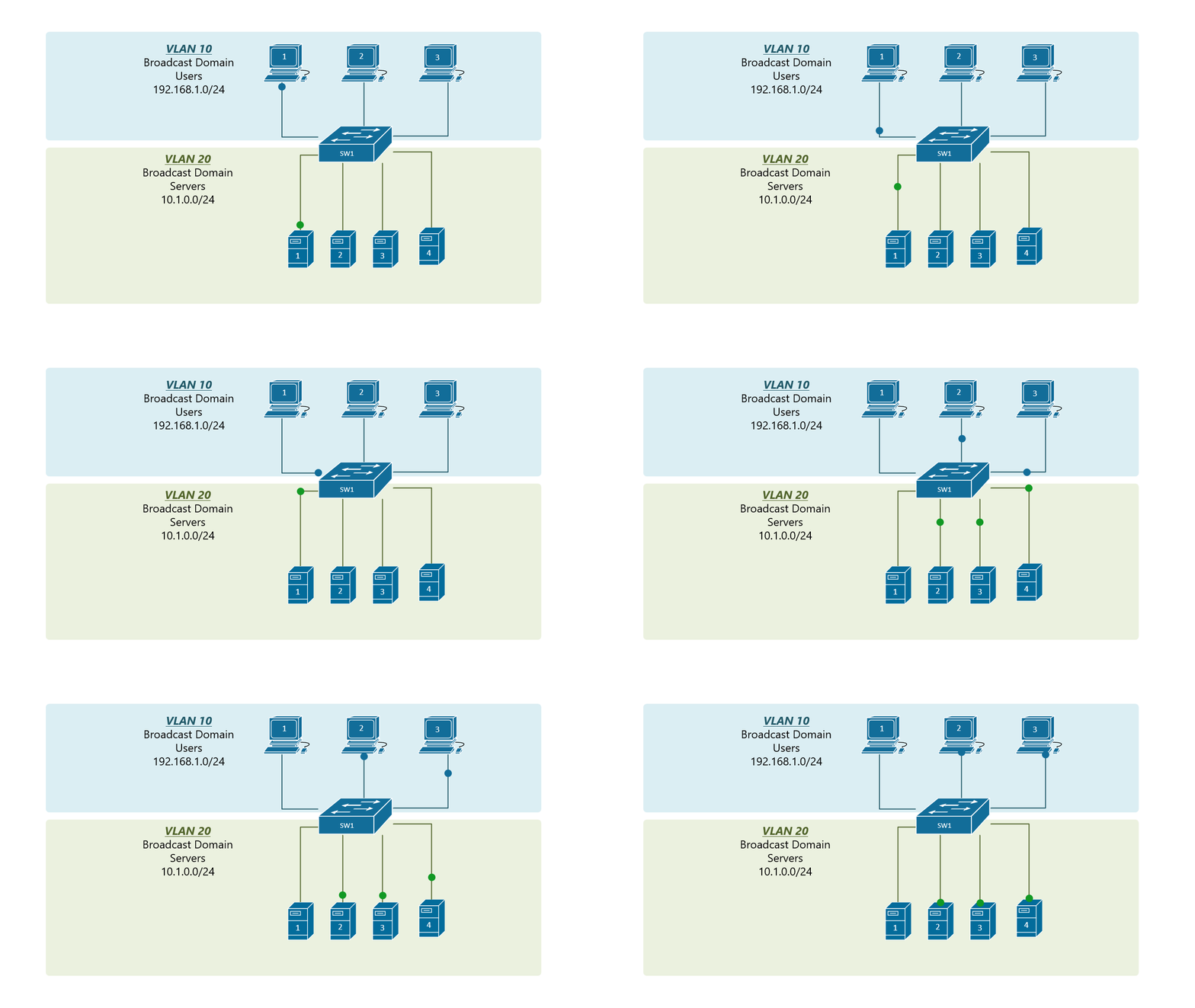
Untagged frames do not have a VLAN tag and look like this... as mentioned VLANS are like virtual switches.
VLANs.gif


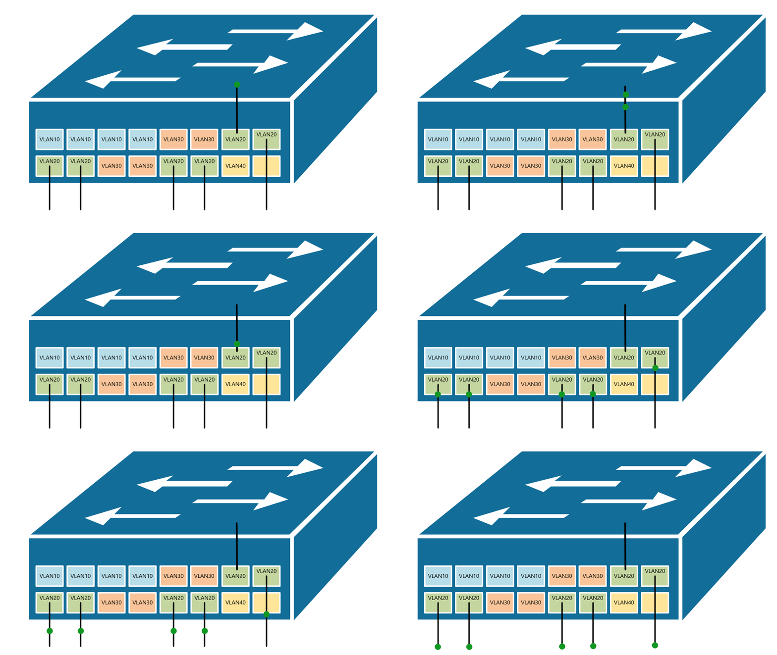
Physically, it looks like this (different switch ports are configured in different VLANs... It's simply a mapping):
VLANs%20per%20port.gif


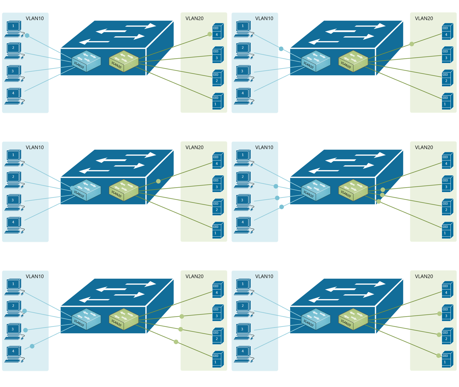
This is what the Virtual Switches or VLANs look like conceptually:
VLANs%20routing.gif


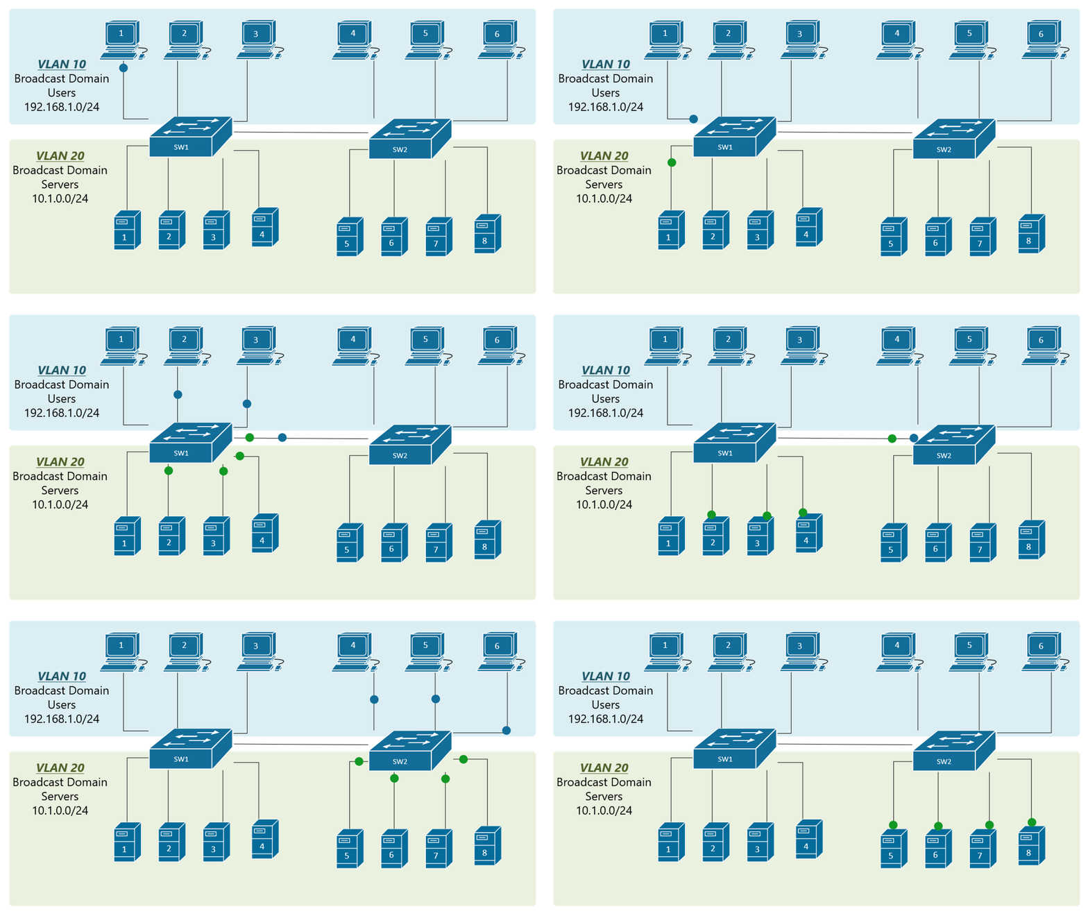
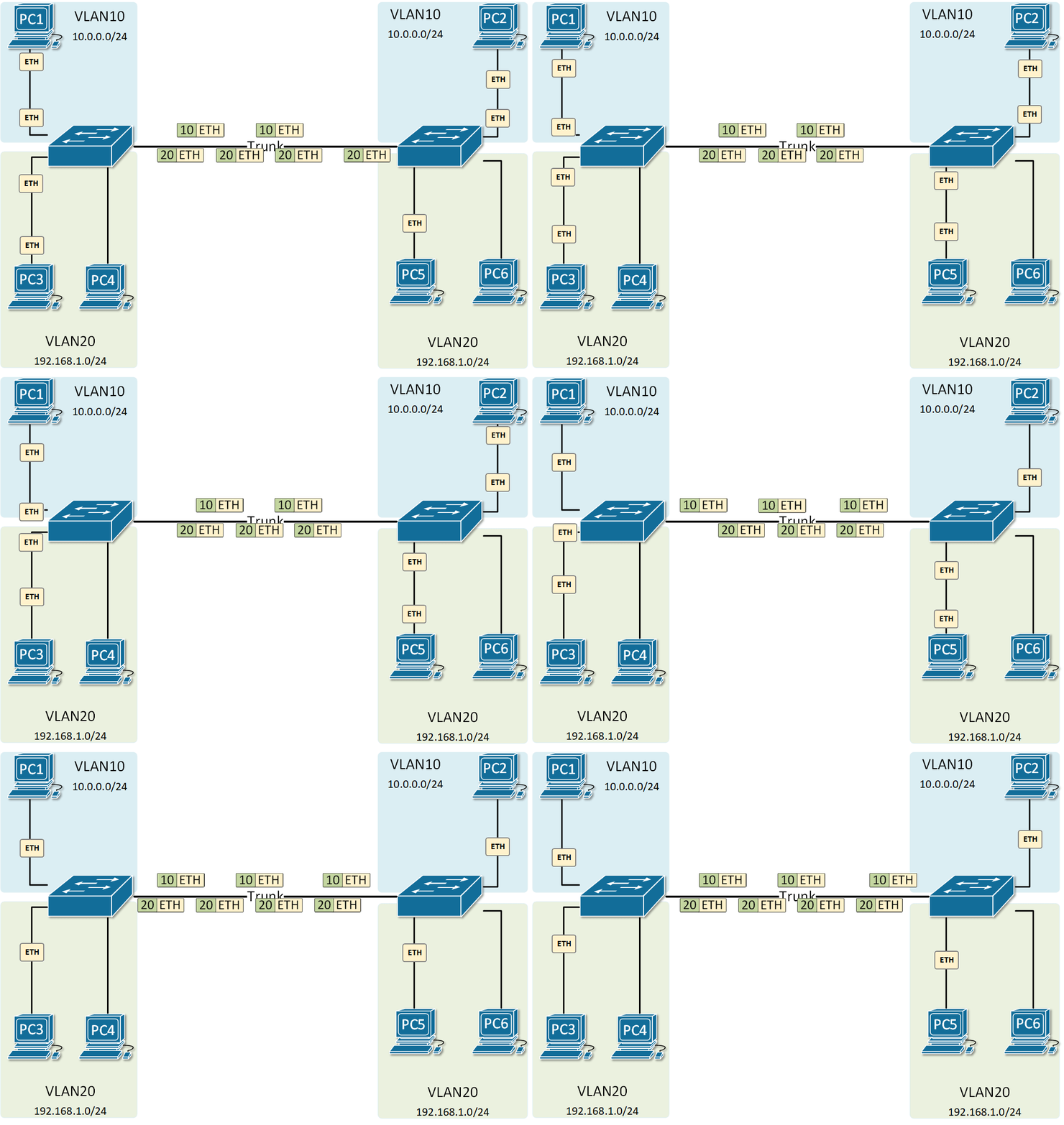
THIS is VLAN Trunking using 802.1q for example:

VLANs%20on%20multiple%20switches_0.gif

This shows the actual FRAMES with 802.1q tags! With those instead of saying ETH, it would have a source and destination MAC address. Then within that would be the packet with a source and destination IP. Within that might be UDP or TCP for a socket.


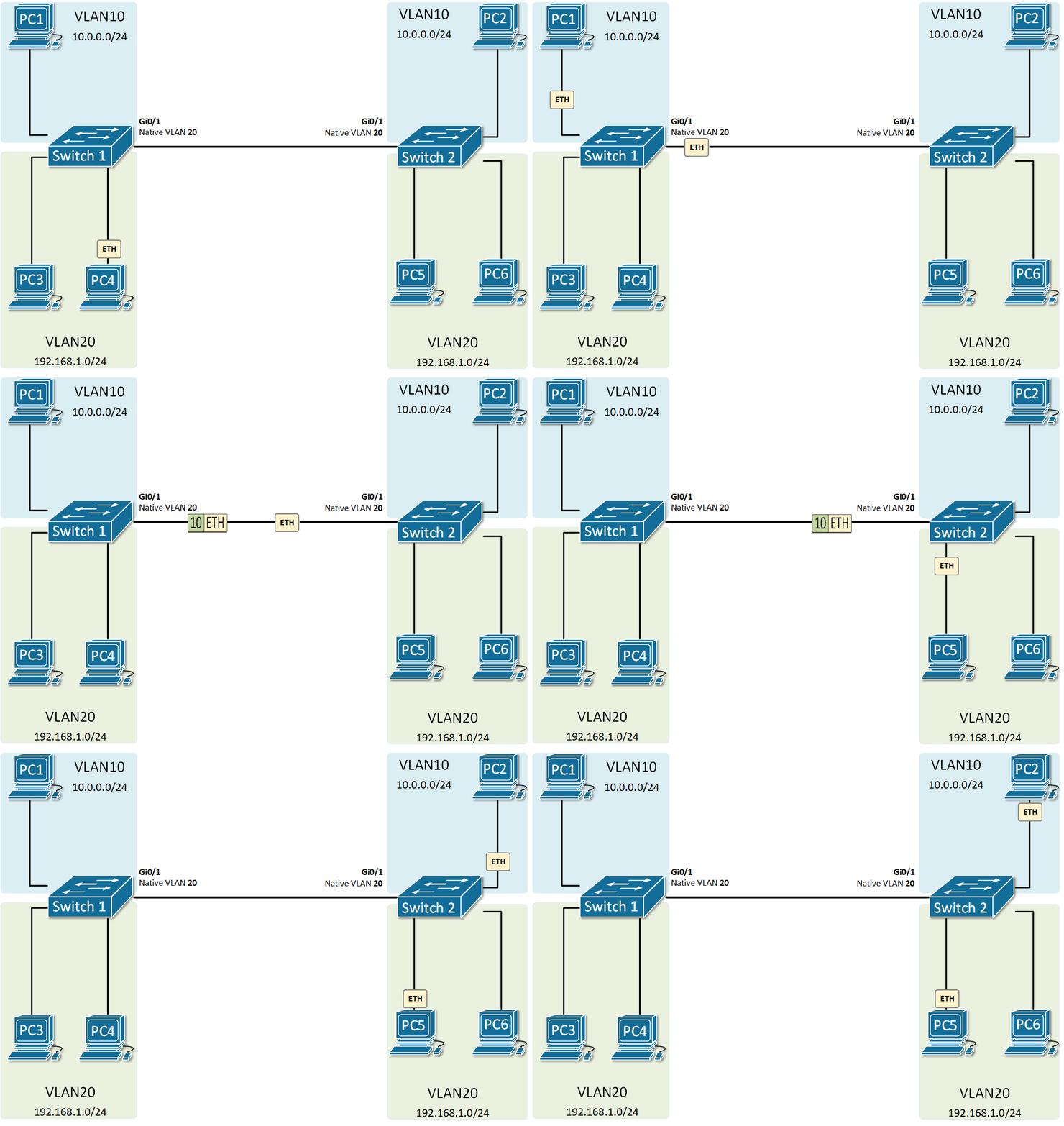
native-vlan.gif


A Native VLAN on a Trunk is what VLAN you drop UNTAGGED "frames" into. This illustration shows that:

native-vlan-2.gif


This shows what a router does between physical switches or VLANS (virtual switches). The router works with PACKETS, which are IP addressed and shoved into FRAMES. There is a source and destination IP address on each packet.

VLANs%20routing%20with%20router.gif

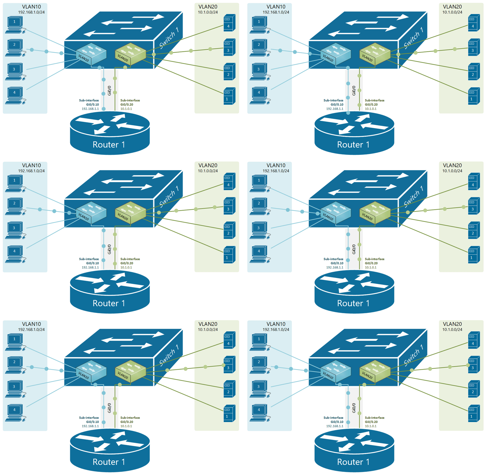
This is Router on a Stick. Don't know why they go into such detail on this in so many network classes, but you can create sub-interfaces within a physicals interface and have each sub-interface work with a different VLAN tag. On the switch you configure Trunk. It looks like this and is merely a router with one (1) cable connected, which happens to be a trunk carrying TAGGED traffic from VLAN 10 and VLAN 20 to the router through the same cable.
Router%20on%20a%20stick%20logical.gif


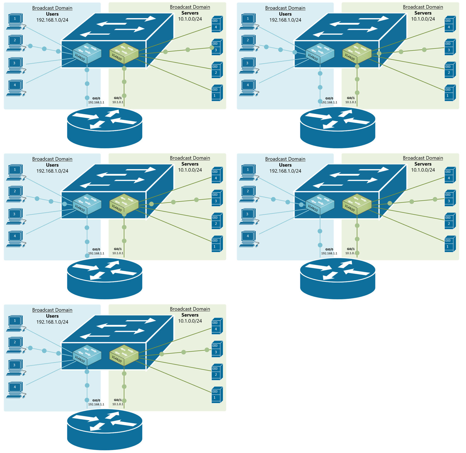
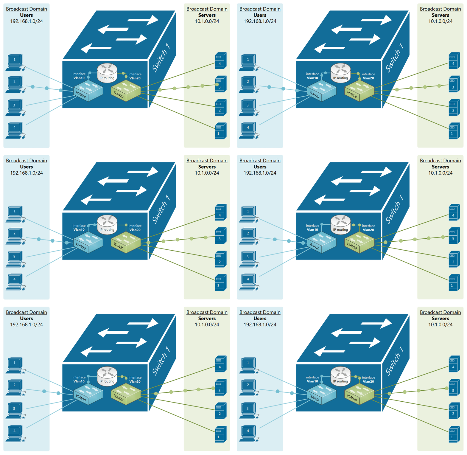
Today you do NOT need a router anymore if you have Multi-Layer switches. Conceptually it looks like this:

Layer%203%20switch%20logical.gif


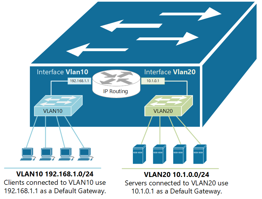
It is configured like this:

inter-vlan-routing-example-1.png


That config would be something like this

vlan 10, 20

interface GigabitEthernet1/0/1
switchport mode access
switchport access vlan 10
!
interface GigabitEthernet1/0/2
switchport mode access
switchport access vlan 10
!
interface GigabitEthernet1/0/3
switchport mode access
switchport access vlan 10
!
interface GigabitEthernet1/0/4
switchport mode access
switchport access vlan 10
!

interface GigabitEthernet1/0/5
switchport mode access
switchport access vlan 20
!
interface GigabitEthernet1/0/6
switchport mode access
switchport access vlan 20
!
interface GigabitEthernet1/0/7
switchport mode access
switchport access vlan 20
!
interface GigabitEthernet1/0/8
switchport mode access
switchport access vlan 20
!
interface Vlan10
ip address 192.168.1.1 255.255.255.0
!
interface Vlan20
ip address 10.1.0.1 255.255.255.0
!


Source of animations: networkacademy.io
 
Well… it’s tough to follow that.

I only want to add that MOST voip phones will let you tag the port and switch port on the phone. So you can have this a single Ethernet line coming from a switch connected to a phone that might be on VLAN100. On the PC port of the phone going to the computer, but on the phone we can tag that PC port to be on VLAN10. This would result in a single Ethernet line to an office jack but separating the phone and PC.

I don’t have any fancy graphics or animations. ☹️
 
Back
Top